Cable Grounding Methods

Cable Grounding Methods
1. Introduction
In electrical installations, grounding serves the purpose of ensuring human safety as well as maintaining the security and continuity of the system. Nowadays, many electrical circuit components, apart from electronic devices, are microprocessor-based and sensitive to electromagnetic disturbances, similar to electronic devices. Grounding is classified into three different types: protective grounding, operational grounding, and lightning grounding. Operational grounding rules, especially for medium and high-voltage grids, may vary according to each country’s regulations. In Turkey, separate guidelines are provided for grounding practices in high and low-voltage electrical power systems and information technology and communication equipment through the “REGULATION ON GROUNDING IN ELECTRICAL INSTALLATIONS” due to the distinct characteristics of these systems.
2. Occuring Magnetic Field
Wires can be manufactured according to the installation and environmental conditions they will be used in, with metallic armor, wire or tape shielding, or a combination of both features. As is known, all conductors carrying current in alternating current systems generate a magnetic field (EMF). These magnetic fields will induce a current on the metal armor of cables produced with shielding. The magnitude of this induced circulating current is directly proportional to the current passing through the conductor. If there is a non-magnetic metal armor (anti-magnetic) on the cable, it will be less affected by the magnetic current, but a small circulating current will still form on the armor.
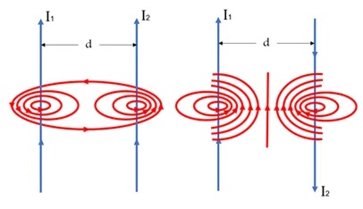
In dual-core (two-wire) cables or in two separate single-core cables that supply a single load, such as phase and neutral lines (L-N), the resulting magnetic fields (EMF) will be opposite to each other. As a result, these fields have negligible magnetic effects on each other. Therefore, whether both are bundled in the same channel or individually shielded, they hardly induce any magnetic current, ensuring minimal circulation current. This principle also applies to three-phase circuits.
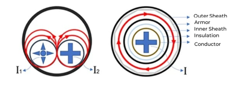
When an electrical conductor carrying alternating current is surrounded by a material rich in metal, such as steel-wire armor or an iron pipe, it generates a much stronger magnetic field. It’s important to note that these circulating currents will lead to increased losses and heating of the cable. The screens used in cables operate based on the same principle. Cable screens protect the signal carried by the conductor from external electromagnetic interference and reduce electrical noise, ensuring that the quality of the transmitted signal remains uncompromised. However, for this process to be fully effective, proper grounding of the cable screen is necessary. Additionally, the phase sequence, arrangement, and installation type of cables are crucial factors.
3. Cable Assembly Methods
Single-core cables can be mounted using different methods. The main ones are the “cloverleaf” (triangular) and “flat” (rectangular) mounting methods. Each type of mounting has its own advantages and disadvantages. Depending on the chosen mounting method, it’s essential to consider its impact on the cable’s current-carrying capacity.
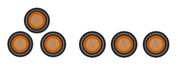
Cloverleaf(triangular) method Flat(rectangular) method
One of the main reasons for mounting cables in a “cloverleaf” (triangular) shape is to ensure that the cable conductors are positioned at equal distances from each other. This minimizes the magnetic fields generated per phase and reduces circulating eddy currents, resulting in lower losses. Cloverleaf mounting is commonly used in low and medium voltage applications due to its ease of installation and space efficiency. However, compared to flat mounting, it has lower heat dissipation, which can negatively impact the current-carrying capacity.
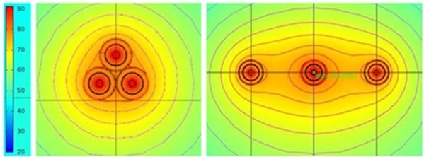
Heat Spreading
This method has better heat dissipation, which results in higher current-carrying capacity compared to “cloverleaf” (triangular) mounting. However, flat mounting requires a wider area. In three-phase systems, the cables belonging to other phases around the central cable can be adversely affected by their magnetic fields. This negative effect can lead to high operating temperatures and voltage imbalances in the central cable. To prevent such issues, grounding the screens or armoring of the cables is essential.
4. Types of Grounding Cables
4.1. Single - Point Bonding
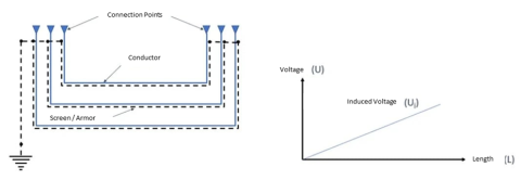
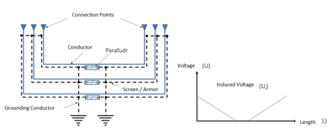
One of the simplest methods used for grounding the cable screen or armor is single-point grounding. In this method, the cables are grounded at only one point along their length to neutralize circulating currents or prevent the circulation of external fault currents. The induced voltage between the cable sheath and ground (or between adjacent screens/armor) is proportional to the cable length and current, reaching a maximum at the farthest point from the grounding connection. However, because one end of the screen or armor is left open, there is no current circulation. As a result, screen or armor losses are minimal or none. For this grounding method, the open ends that are not grounded are important of isolation resistance since maximum voltage ratio is induced on the open ends. Therefore, isolation must be applied with quality.
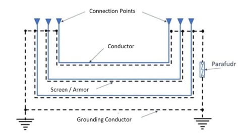
In single-point grounding systems, fault currents from external paths with ground faults can return. A ground fault occurring near the cable route can lead to an increase in potential difference between the two ends of the grounding system. This situation poses risks to human life and equipment. To safely redirect ground fault currents back to the ground and limit potential differences, parallel grounding conductors are used in single-point grounded systems.
4.2. Split - Single Point Bonding
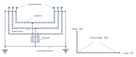
This cable grounding method, as the name suggests, operates on the same principle as single-point grounding. However, it is more suitable for longer distances compared to lines grounded on one side. It can be applied to address various requirements by connecting the ground at different points.
4.3. Both - Ending Bonding
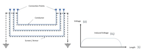
The method of grounding from both ends, also known as “two-point bonding,” is one of the most common and straightforward grounding techniques. It is also the most economical method for cable grounding. In this grounding method, unlike single-point grounding, there is no need for a surge arrester. Instead, a grounding conductor is run parallel to the cables to equalize the potential difference.
However, it’s important to note that in this grounding method, circulating currents continue to flow on the screen/armor of the cable, leading to cable heating. As a result, losses increase, and the cable’s current-carrying capacity is negatively affected. To mitigate the adverse effects of circulating currents, it is often preferred to arrange the cables in a trefoil (triangle) configuration.
4.4. Cross Bonding
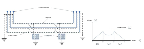
The cross-bonding method, also known as “cross-earthing,” is suitable for use in longer-distance lines compared to other methods. In this method, the screen/armor of phase cables, which are divided into system sections, is connected to each other in a crosswise manner to reduce induced voltage and circulating currents. The main reason for this is to ensure that the induced voltages between the cables cancel out vectorially with a 120-degree phase difference. By nullifying the induced voltage, negligible circulating currents can occur on the screen/armor. Typically, arranging the cables in a trefoil (triangle) configuration is preferred in this method. This helps further reduce losses caused by the system, positively impacting the current-carrying capacity of the cables. However, due to the need for additional materials and more technical work, this grounding method is considered the most expensive among grounding systems.
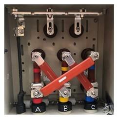
Crossover Box Connection Example
5. Conclusion
Selecting the appropriate grounding method depends on various parameters. Factors such as the cable route, the length of the line, the geographical location of the chosen route, and the manufacturer’s production specifications all play a crucial role. Additionally, cost calculations for the equipment and materials to be used are essential.
When it comes to economic energy transmission, analyzing the cost implications of losses is equally important. Remember that each situation may require a tailored approach, considering these factors to determine the most effective grounding method.
Türk Prysmian Kablo ve Sistemleri A.Ş.
e-posta: [email protected]


